Digital PDP 11/05 S in BA11-K
SHARE |
|
 Digital PDP 11/05 S in BA11-K
 |
by Bill Degnan - 10/01/2015 11:17 |
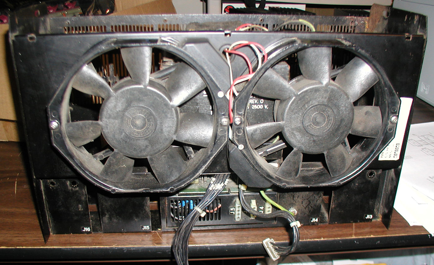 Started working on piecing together a PDP 11/05 S in a BA11-K Mounting Box. Pictured here are the fans that cool the H765 power supply's transformer. Note there are no DC voltage bricks installed. I removed the metal fan covers (they were rubbing the fan blades when you spin the fan manually). Click for larger view.
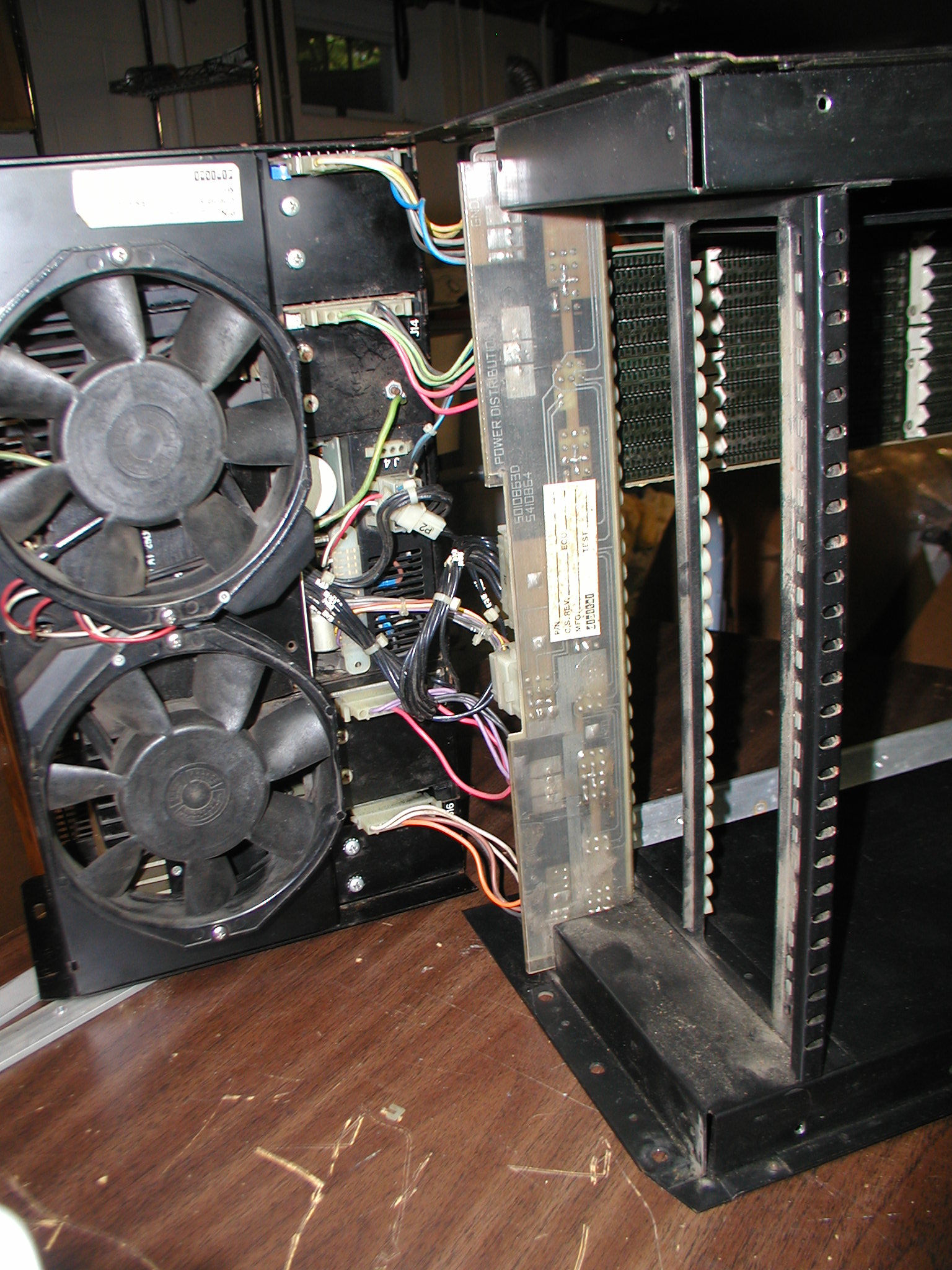
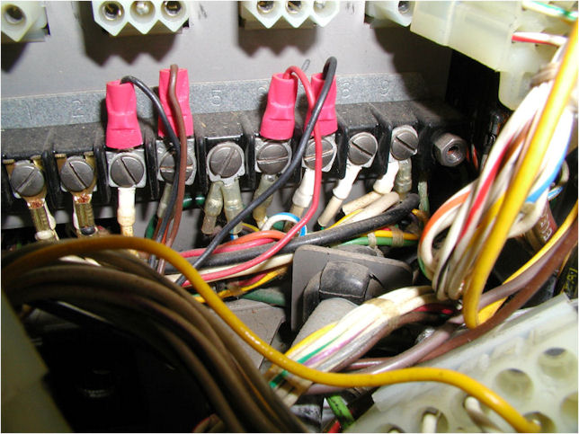
 This is a view of the power distribution board installed in the PDP 11/05 S chassis. The connectors attach to the H765 power supply. First I need to assemble the parts. Next I will test the voltage regulators with no load and see where this unit stands, power wise. If you click on the thumbnail you can see that a minimum backplane of slots is installed. You can also see a weird connector coming from J3 of the Power Distribution Board, but I think it was installed for testing purposes, The wires that lead to the front panel are separated. There are a lot of redundant power connectors you can use, it's a pretty flexible system.
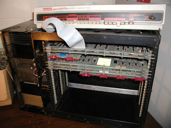
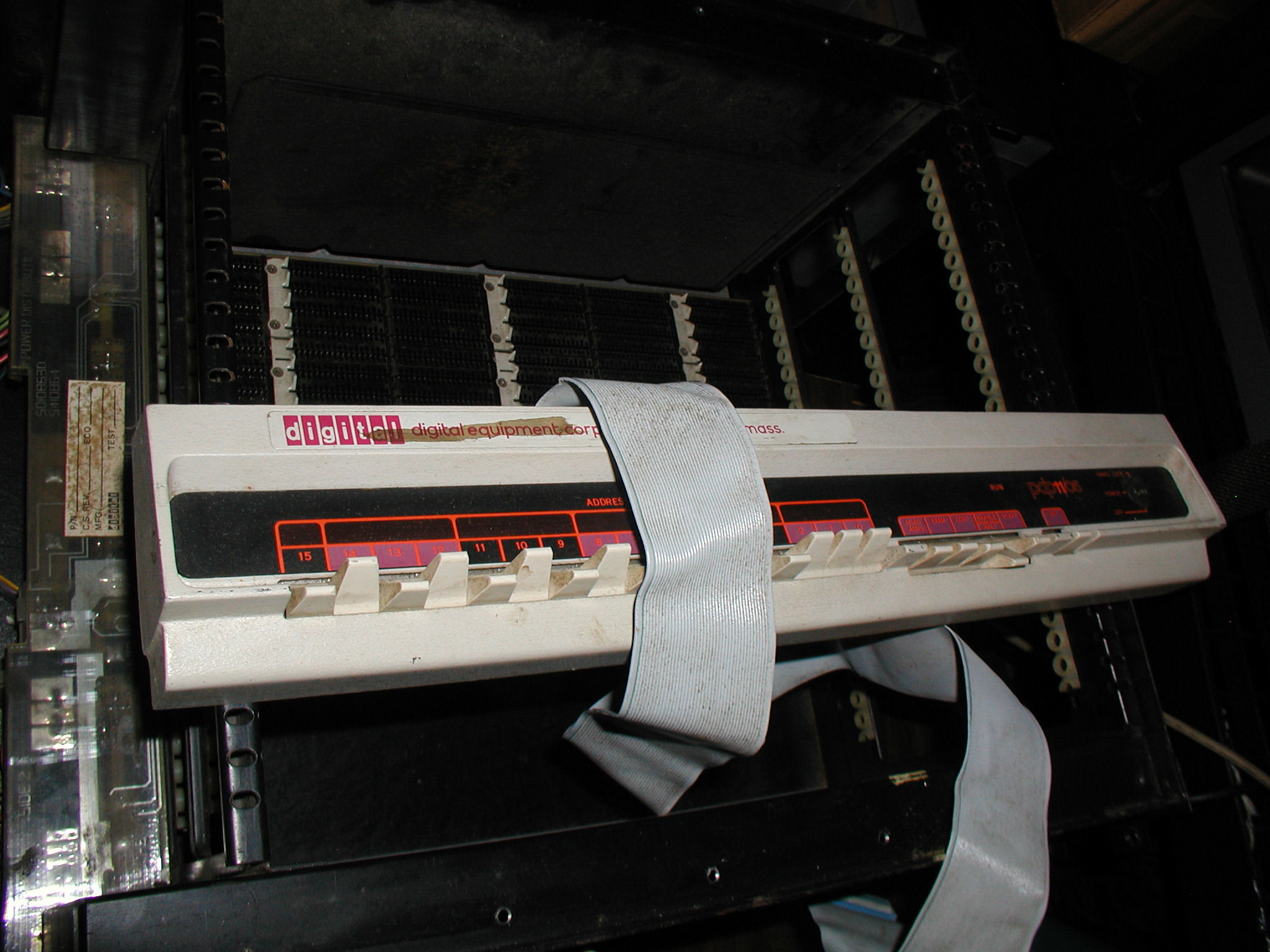 The front panel switches and cable.
Depending on how this goes I can alternatively transplant the backplane into my PDP 11/40 that needs more slots. Not sure yet. More pictures Reply |
|
 Diagnosis - Voltage Regulator Issues
 |
by Bill Degnan - 10/02/2015 12:54 |
|
-5 and +5 V lines are bad, need to take a look at the voltage regulators.
Reply |
|
|
Replace h754 |
by Bill Degnan - 10/04/2015 18:56 |
|
Replaced h754 20v/-5v voltage regulator in order to restore -5 V service to backplane. I now need to find or fix two working h744's to bring +5v into the system. I had 3 spares to try but none worked (did not have high hopes). I will see if I have others, and/or will diagnose the three I have, determine what's wrong and fix.
Reply |
|
|
Simple RAM Testing |
by Bill Degnan - 10/08/2015 10:43 |
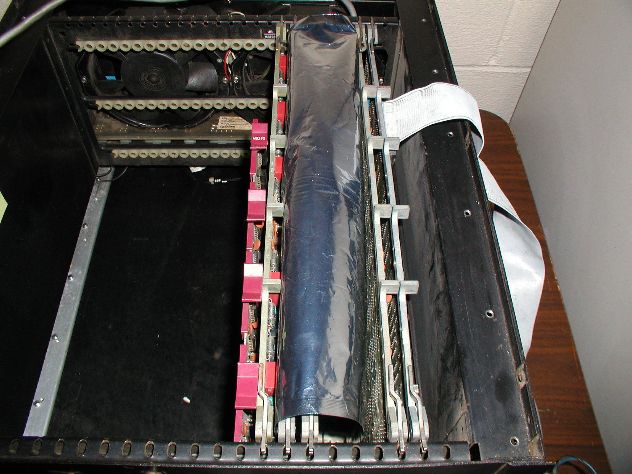
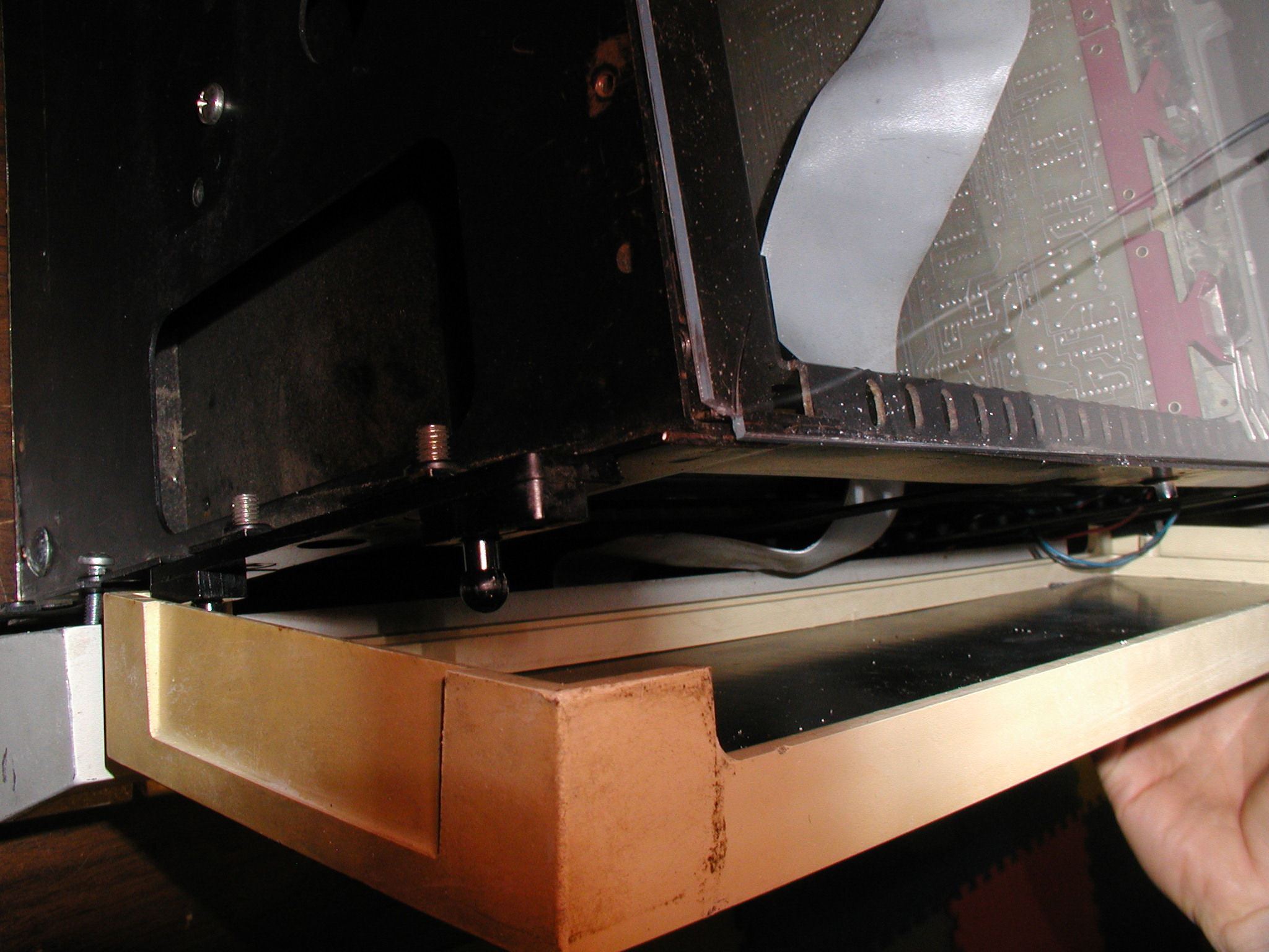
 This is an image of the H765 power supply connected to BA11-K from the top view (with system on its side). The power supply can remain wired for testing this way. After replacing the h744 voltage regulators and probing the backplane test-points to verify correct voltages, the chassis was re-assembled. Click image for larger view.
h765 to Backplane 2 h765 to Backplane 3 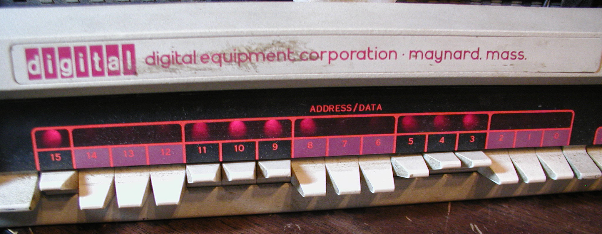 The front panel responds to load address, exam, deposit toggles from the front panel but not reliably. Note bit 8 is stuck in this photo. Stuck bits "unstick" with a little play using the front panel, but I need to get to the point where this is not necessary. Click image for larger view.
Address Load 2 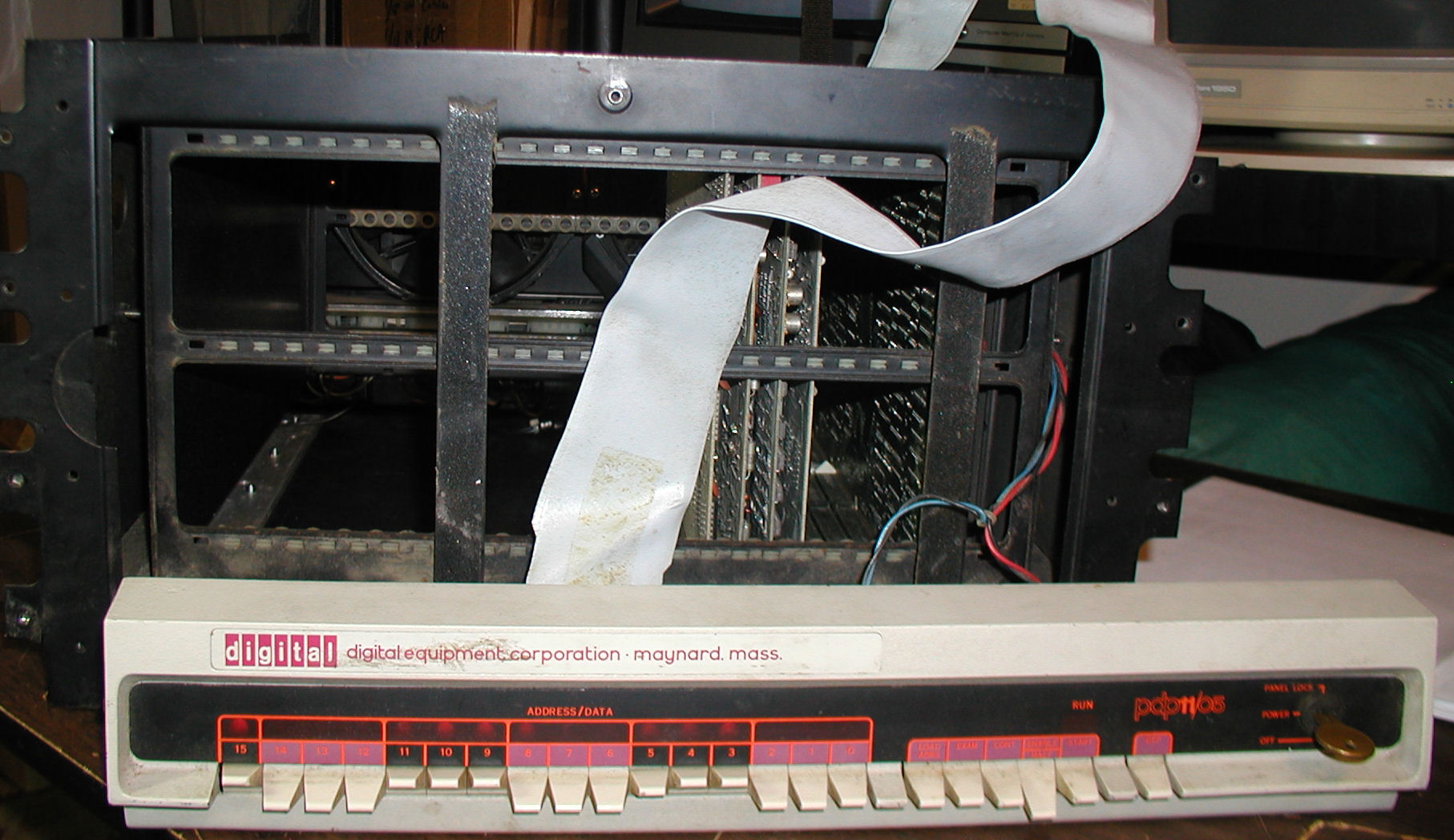 View of PDP 11/05 S system from the front
NEXT: See if RAM bit stickiness can be worked through by exercising RAM, switches, lights. Too early to make a diagnosis. Need to run a CPU and timing test. Reply |
|
|
Testing Continues |
by Bill Degnan - 10/09/2015 21:24 |
|
DC LO AC LO look good. (adjusted the +20 up a hair on the h754)
I transplanted the CPU cards into another system to test and they work there. I re-installed the CPU cards and cleaned the RAM pins with DeOxIt. I was able to load the CPU test into RAM and run it: 1777700 240 1777702 777 Issue - when I attempt to write to an address using address or data switch 5, I often can't unstick the light even when in the down position or should not otherwise be lit. Sometimes I can't run the CPU test because the system does not let me load the correct address into the program counter. Maybe there is front panel switch problem. To test the front panel switches: 1. Power off the system and disconnect the console cable from the M7260, leaving the power connection to the front panel intact. 2. Power on, lights 177777 should be lit up. 3. Next, put a jumper on pin F of the M7260 CABLE holes (6th from bottom) and on the other end connect to selected pins on the cable to activate certain lights: F to GND - 000000 (pin hole on the cable #1) F to N - 125252 (pin hole 6) F to L - 146314 (pin 5) F to J - 170360 (pin 4) F to D - 177400 (pin 2) The front panel passed the test. Narrowing things down, next I need to check RAM or the RAM support boards. The system has 16K Core G235 (xy drive module) H217D (memory stack) G114 (sense / inhibit) M8293 (memory control module) G114 seems ok See also: http://www.shiresoft.com/pdp-11/11-10/index.html I read up on the parity/non parity thing. Given the system has 217D printed on the chassis it must be a MF11-U backplane (U=no parity amd UP=Parity). The "MF11-U/UP core memory maintenance manual" may help explain if it is possible to switch between 217C and 217D. Basically if I want to use 217C I need to put a M7259 in slots A-B on an open card hole. The m7259 is "parity control" but I need to read up on jumpers and all of the cards associated with the core memory system. It's do-able though. DEC-11-HMFMA-B-D MF11-U-UP Core Memory System Maintenance Manual.pdf Reply |
|
|
Parity vs Non-parity core RAM |
by Bill Degnan - 10/12/2015 17:06 |
|
I will have to add (or remove?) the RAM parity jumper to the backplane if I want to use the BA11-K for 11/40's H217C core RAM testing because the backplane is wired expecting a pdp 11/05 S chassis, which uses non-parity RAM (h217D). As I stated earlier it would be nice to be able to test RAM using the BA11-K because I know everything else more or less works.
Currently the no parity RAM set I have installed is not inhibiting correctly address line 2 (or whatever you call light 2). When I deposit into line 2 the data light comes on (i.e. 000 100) but nothing shows when I re-examine. I can load address 000 100 (the light works) and I have tested the front panel (lights work). There are only four cards used by non parity RAM because you don't need the parity card. Of these, the G235 (I think) does the write inhibit to the h217D's core stack. Hopefully the core itself is OK and the issue is with the write being done by the G235 (fix or replace this card). One other thing...It may be that the -15 is too low (?). The -15v is reading as -17.16 off the backplane. The docs say it needs to be within +/-5% (i.e. no more than -16.5v). I understand that the h745 is for +15v and -15v but I don't know which voltage is effected by the one adjustment pot on the h754 regulator. If it's not for the -15v line then I have to disassemble everything and make adjustments to the h765 itself directly. Ug. I read the entire 122 page core RAM manual and read about how the -15V line is used. I would think all lines would be bad and not just one if the -15V was too low and not just one line. So I am leaning to thinking the -17v is not the source of the problem. I am getting good DC LO / AC LO and the CPU is running properly when run the CPU test. Reply |
|
|
MF-11-U Core Testing |
by Bill Degnan - 10/14/2015 11:06 |
|
The BA11-K Mounting box manual explains how the -15V is generated, and I was able to adjust the voltage down (-16.1 to -15) with by adjusting the potentiometer on the H754 regulator. Not sure why it was over -17v when I first tested it, perhaps using it cleared out the cobwebs, or maybe the large cap is weak. Either way, moving on.
Consulted the DEC-11-HMFMA-B-D MF11-U-UP Core Memory System Maintenance Manual See page I-4, it pretty much spells out how the cards work. I tested four G235 XY Drive modules, one was clearly bad, the other three seemed to be OK. While installed they all caused the computer to operate the same way, everything else being the same. Data/Address line #2 will not inhibit (set bit to 1). I think I can eliminate the X-Y driver function as a source of the problem. Next I tested two M893 modules. These assign the RAM space, handle UNIBUS timing, read write control logic. All of the M893's on hand work, no change I still have a stuck 2nd bit. Next I tried another G114 - This was the problem. Now I have working RAM! Reply |
|
|
Testing Your Digital UNIBUS PDP11 |
by Bill Degnan - 10/15/2015 08:14 |
|
Reply |
|
|
Hello World ASR 33 Test |
by Bill Degnan - 10/21/2015 09:08 |
 PDP 11/05 prior to configuring for Teletype. Click for larger image.
Attaching a teletype to the PDP 11/05 S is nearly the same as the 11/05 NC. First verify that your M7260 CPU card (the one with the front panel cable) switch S1 is pointing to position 5 (and not backwards pointing to #2). Next attach Berg end of the relatively short 70-08360 cable to the M9970 card installed in slot A-B (not C-D!). NOTE: I also have a GC card installed in slot D of the same card row. Attach the other end of the 70-08360 cable mate-n-lock connector to the teletype. You can read more about this here. What is most important is to be sure mate-n-lock pin 7 attaches to terminal strip connector 4 on the teletype. pin 5 goes to terminal strip connector 7, pin 3 goes to terminal strip connector 4, and pin 2 goes to terminal strip connector 3. If you connect your computer to the teletype in LINE mode, power on the computer, and the teletype stops chattering you at least have a current loop. Next, run the Hello World program from the front panel. Hello World! directions. Remember after toggling in the program to start from 001020. A lot of little things can go wrong, but you can learn more here: Teletype 101. I was able to get this working. At this point I have a system that can interact with a teletype for I/O. TTY I/O Echo Characters Demo NEXT: Memory is not stable. Reply |
|
|
RAM Shielding |
by Bill Degnan - 11/29/2015 21:34 |
 Anti-static bag inserted between rear of H217D core card on one side, and between the M930 terminator and M7261 CPU card. Since this photo was taken, the bag was cut to fit. Click image for larger view.
I tried a number of core stack cards and combinations. The issues were strangely similar even though totally different cards were inserted. For example address 13 would stick high even after all available cards swapped out. So, I decided it must be an electrical problem that I might be able to solve by inserting shielding behind the core stack and behind the CPU card. That's what you see here, an anti-static bag folded over between the cards that would most be effected by shielding problems. Worked perfectly and since the shielding was installed there have been no stuck bits. NEXT: Load BASIC via papertape? Reply |
|
|
Video PDP 11/05 S runs BASIC program |
by Bill Degnan - 12/11/2015 08:14 |
|
This clip is for Mike W. who wanted to be able to isolate the sounds of a person typing at the ASR 33 Teletype. This video demonstrates how to start BASIC already in core memory from a cold start, enter a BASIC program, edit it, and run it with output going to the Teletype printer. Reply |
|
|
Chassis Covers |
by Bill Degnan - 01/18/2016 13:58 |
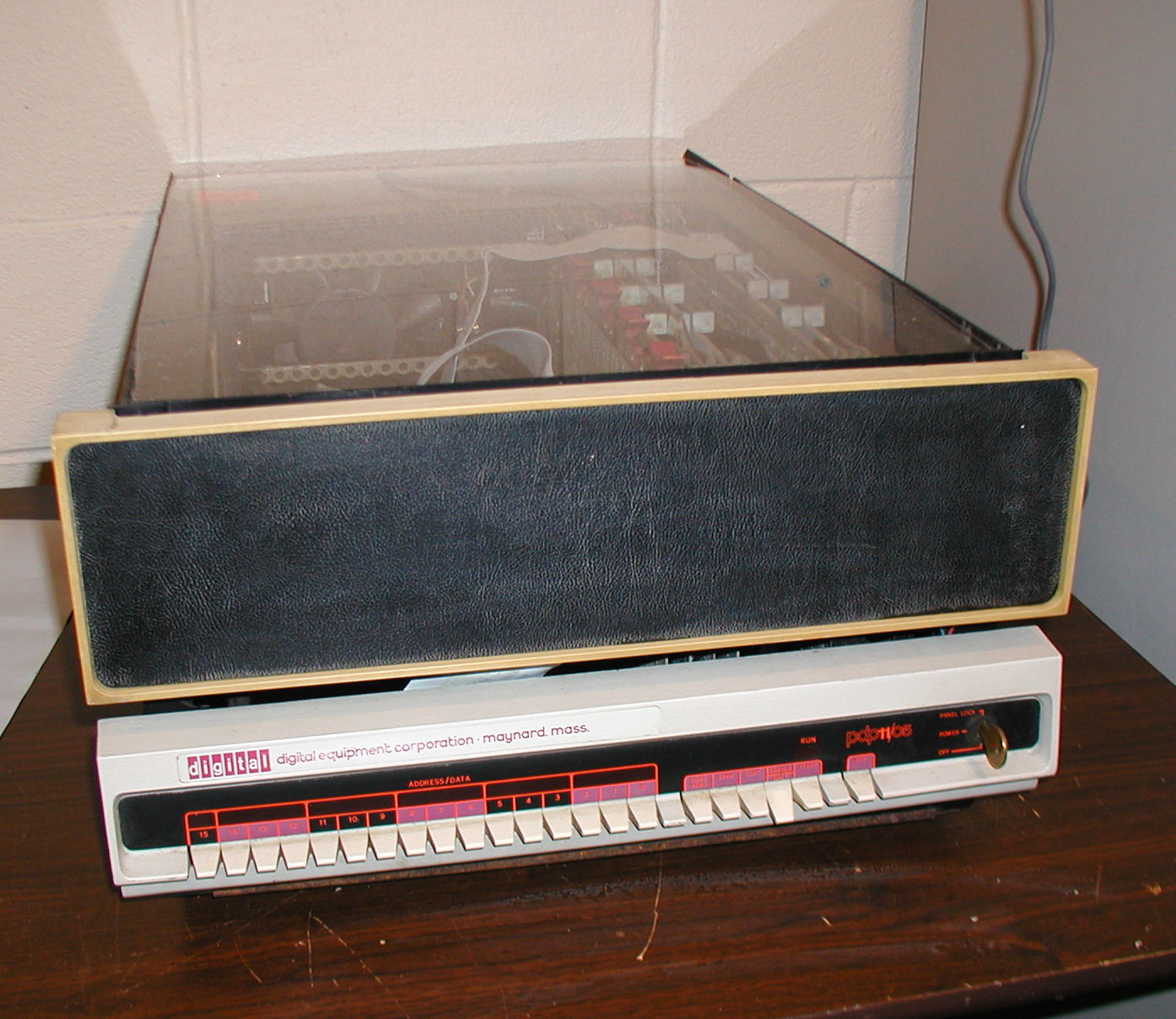 Found a discarded piece of Plexiglas that almost fits perfectly on the top, and added a front panel cover. The cover had two broken-off pegs in the holes so I used a drill press to auger them out. I am still missing the piece that fits behind the front panel. Click image for larger picture.
UPDATE: ...I see I never posted anything in this thread to mention the fact that I was able to load BASIC via papertape. Although I ripped a tape and needed to patch it, there were no issues I was able to load without problems. For the past few months I have been able to fire up the computer, attach to my Teletype and fire up BASIC from 000 000. Right Front Chassis Cover Bracket Left Front Chassis Cover Bracket Cover Applying Reply |
|
|
Replaced h745 -15V |
by Bill Degnan - 08/21/2018 17:42 |
|
When the -15V voltage regulator fails the current loop connection between the 11/05 and a teletype fails. This symptom was confirmed by measuring the -15V off the backplane. h745 replaced and service has been restored. Not sure what component on the bad h745 failed.
Reply |
|
Resources:

Popular Topics and FAQs
Past Issues:
Before we switched over to a blog format, past page archives here:
Vintage Computer Festival East 3.0 June 2006
Commodore B Series Prototypes July 2006
VOLSCAN - The first desktop computer with a GUI? Oct 2006
ROBOTS! - Will Robots Take Over? Nov 2006
Magnavox Mystery - a Computer, or? Jan 2007
The 1973 Williams Paddle Ball Arcade Computer Game Feb 2007
The Sperry UNIVAC 1219 Military Computer May 2007
VCF East 2007 - PET 30th Anniversary June/July 2007
The Electronic Brain August 2007
Community Memory and The People's Computer Company October 2007
Charles Babbage's Calculating Machine December 2007
Vintage Computing - A 1983 Perspective February 2008
Laptops and Portables May 2008
From Giant Brains to Hobby Computers - 1957 to 1977 August 2008
Historic Computer Magazines November 2008
World's Smallest Electronic Brain - Simon (1950) December 2008 - Feb 2009
Free Program Listings Spring 2009
Computer Music Summer 2009
Popular Electronics Jan/Feb 1975 - Altair 8800 Fall 2009
Early Microcomputer Mass Storage Summer 2010
Flexowriter
This image was selected at random from the archive. Click image for more photos and files from this set.