Donner 3500 - an early portable computer
SHARE |
|
 Donner 3500 - an early portable computer
 |
by Bill Degnan - 05/25/2009 17:58 |
 The 1959 Donner 3500 portable analog computer. Click for larger image.
Pushing the exploration of portable computing one giant step farther (for me), here is a quick glimpse of the Donner 3500...My copy of the instruction manual was published in 1960, after Systron merged with Donner to form Systron-Donner Corporation. The manual depicts a Model 3500 with leather handles on the sides. The computer I have has metal handles on top, and I am unsure if this means it's an earlier model made before the merger or if the handles were added by the owner. Because they are symmetrical, I'd like to believe that they are factory/original handles. Also, this computer's serial number is 107, which also indicates an earlier version. Serial numbers can be deceiving however. The computer id plate on the back of my 3500 says "Donner Scientific Company". I do not have the "3571 Potentiometer Strip" option installed to the top back of the 3500, indicating that this computer may have been used with an external control device or oscilloscope. Pictures NEXT: Post a PDF of the instruction manual. Reply |
|
 Donner 3500 Schematic
 |
by Bill Degnan - 05/29/2009 10:37 |
|
Donner 3500 Schematic
Reply |
|
|
Donner 3500 Tube Layout |
by Bill Degnan - 06/18/2009 22:52 |
There are 6 control boards in the Donner 3500, each has a set of tubes. This weekend I tested every one of the tubes, they all work. I used a Heathkit tube tester.
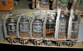 Voltage Regulator card for the Donner 3500 analog computer. This card is inserted into the left most slot on the blue ribbon receptical bus back plane.
Viewing from the back of the unit with the door open: 1) left-most card is a voltage regulator, tubes from left to right: 6BR8 12AX7 12AX7 5651 CK-7044 12BH7A 2) The remaining 5 cards are the same, the tubes from left to right are: 6BR8 ECC 83 / 12AX7 ECC 83 / 12AX7 - NOT A TUBE (It's a relay) ECC 83 / 12AX7 6BR8 3) There are two tubes attached to the chassis to the right of the 6th card. The tubes in this space are both marked OB2 Reply |
|
|
Donner 3500 As Direct Voltage Meter |
by Bill Degnan - 07/17/2014 21:38 |
 Section 3.1 of the Donner 3500 manual. Using the Donner 3500 as a voltage meter. Click image for larger view.
 Plugboard set to match the direct voltage reading schemtic. On the other end, an un-regulated 12V power supply is feeding into the circuit to be metered. Click image for larger view.
 The meter correctly shows approximately 12 volts. Click image for larger view.
So far power up and voltage test return encouraging results. Reply |
|
|
Demonstration Problem A |
by Bill Degnan - 07/27/2014 01:34 |
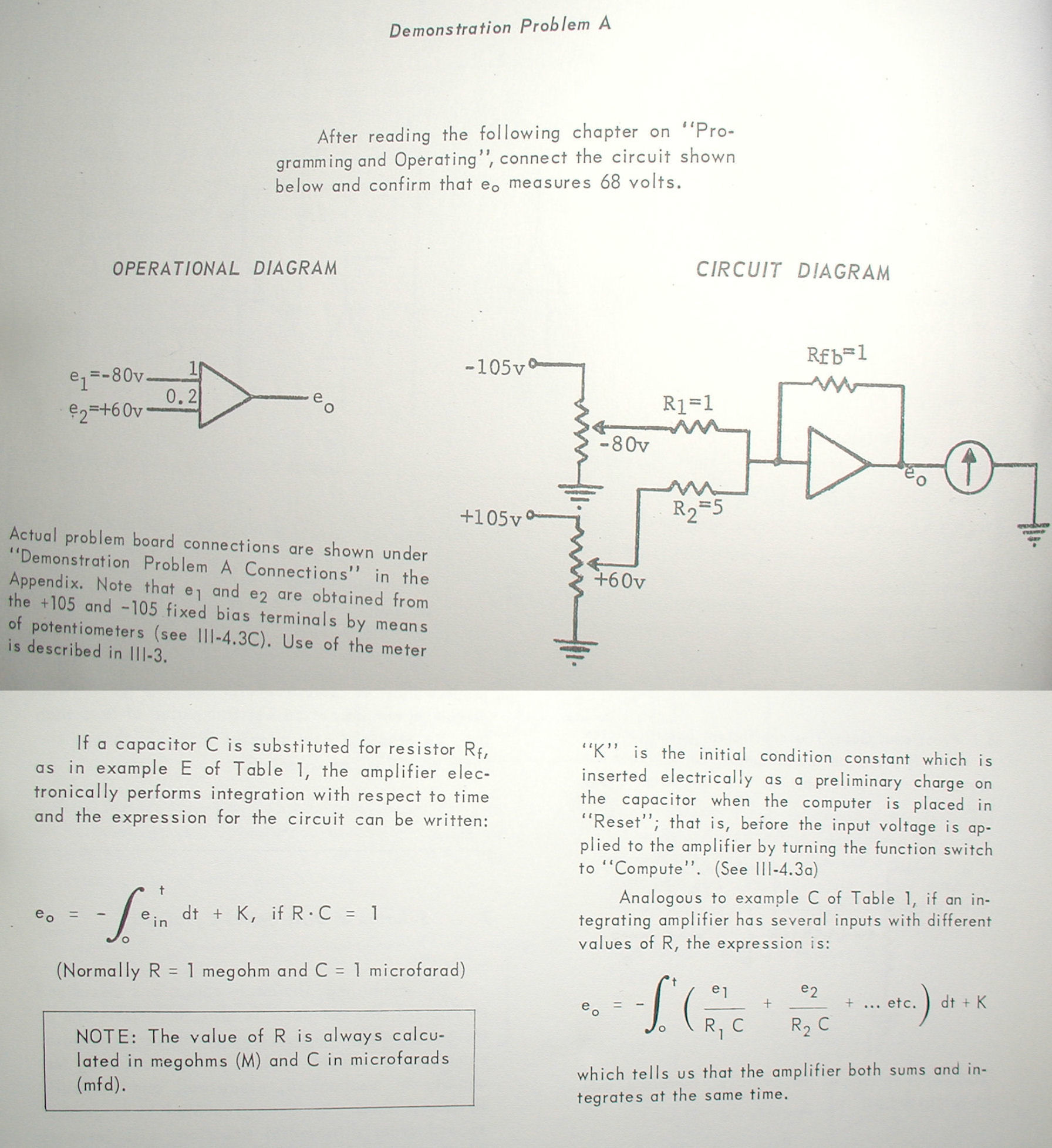 e1 and e2 are obtained from the +105 and -105 fixed bias terminals by means of potentiometers. I don't have a 3500 with the potentiometer array, and the voltages are a little hot as a result (> +/- 105v). Click for larger image.
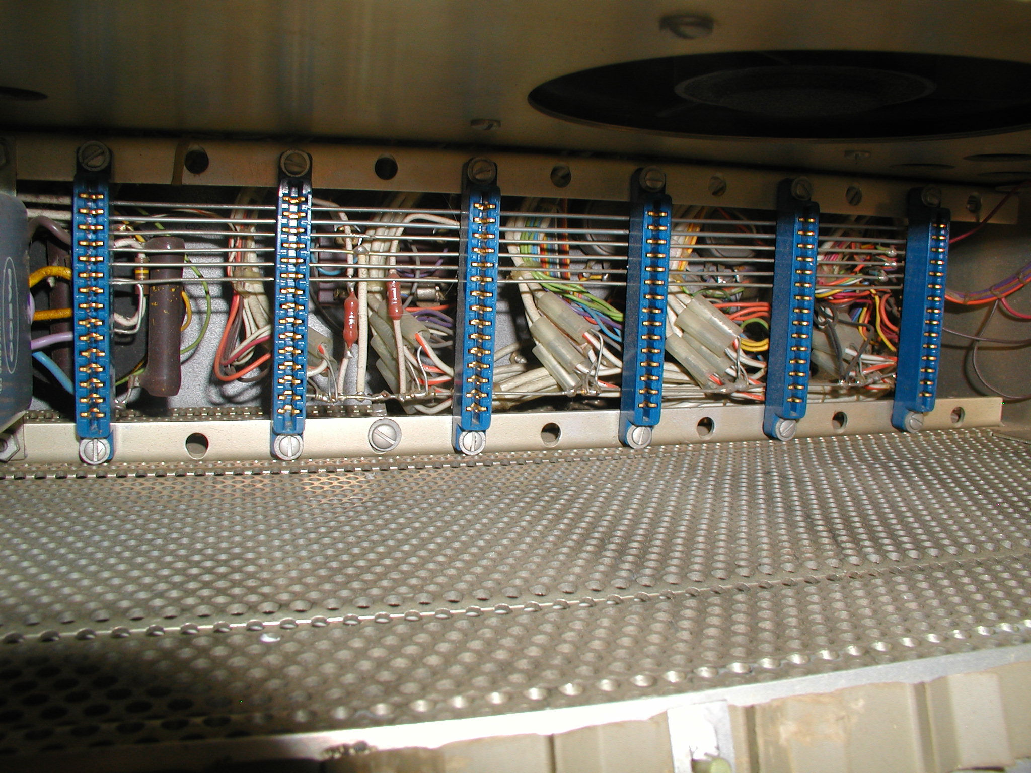
 This photo shows the wiring of the problem. I do not have the special plug board cables that came with this unit, so I had to borrow from other places. The idea here is to solve the equation so that one reads +68 volts at point e0. Click image for larger view.
 The program schematic says the correct resistors to use should be 1 and 5 mega ohms (brown/black/green and green/black/green). I don't have a 5 mega-ohm resistors so I used a 4.7 instead. When I run the program it will display a higher voltage value (less resistance). Click image for larger view.
 The "display" of the Donner 3500 is a voltage meter with a range selection of 100, 30, 10, 3, or NULL. I can also attach to an oscilloscope, but it's not necessary here given I am not measuring any time variances. In this case the voltage scale knob is set to read the range of -100 to +100 volts, and the actual value measured was +90v. The #9 light is out, indicating that there is no over-voltage condition (click image to see this). Overall the display lights are responding as I would expect, but it took a little reading to understand their meaning.
The equation is written for two 1 mega-ohm and one 5 mega-ohm resistors, I'd need to recalculate to see if ~+90v is correct if one substitutes the 5 for a 4.7 mega-ohm.. As I said above I don't have the potentiometer array mentioned (in the 1960 version) of the manual which will also contribute to a higher result voltage. All considered this is a great test, the Donner appears to be functional in general...Click image for larger view. "Demonstration Problem A" Photos Reply |
|
|
Comment about Resistor Substitution |
by Bill Degnan - 07/28/2014 12:49 |
|
Got this message from Dave of the MidAtlantic Retro Club:
"...Bill, I wonder if I get Dave McGu. to distract you with a big VAX so I could pinch this…. … been looking for something like this for ages and the last one that sold in the UK which was nowhere near as nice as this, went for $2.5k but I think as you are state-side you are OK. Any way, If you have 105V in from as you have no pots the output should be (-105) + (1/4.7)x105 which the Windows calculator says is 82. You say you have more than 105, well for +/- 110v in you should get 86v. You meter shows 85 so some where near… I was going to say there is nothing special about the pots in the missing array, well actually there is , they should be happy with 105 Volts across them, and I think of lower resistance than the input resistors for the OP AMP, so I if I have done my sums properly 1 Watt 220K would be OK, but if you have the circuit you will have a value. Then you can set the input voltages as per the diagram. I think a good test would be to use all 1Meg resistors, in which case the output should be “zero” if both input voltages are the same. Hope this helps Dave G4UGM..." --- This comment would contradict my guess that a smaller resistor would return a larger voltage. I will see what happens if I exchange the 4.7 for a 1 mega-ohm resistor. If Dave is correct, then I need to also check all voltages along the circuit to see what is truly happening. Reply |
|
|
Video of Demo Problem B Solution |
by Bill Degnan - 07/28/2014 13:04 |
|
Video of Donner 3500 in action. This time to demonstrate the rate a capacitor drains. This problem is described in the manual. I had to improvise, but it's good enough for this demo:
http://youtu.be/2HT7scFacZE Reply |
|
|
Plug Board Modules |
by Bill Degnan - 08/24/2014 21:03 |
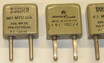 Donner 3500 plugs with built in capacitors. Courtesy Computermuseum der Fakultät Informatik in Stuttgart, Germany
From an Internet search I found that the Computermuseum der Fakultät Informatik in Stuttgart, Germany also has a Donner 3500. I asked them about the plugs, and to see if they had a list of the original values. Link: http://computermuseum.informatik.uni-stuttgart.de/ They have the custom plugs that originally came with the unit. Klemens was kind enough to send me a set of photos which I have added to the same directory linked above, his note below. ------ Original message------ From: Klemens Krause Date: Sun, Aug 24, 2014 6:00 AM To: B Degnan; Subject:Re: Donner 3500 Hi Bill, now I was in the external exhibition and I found the other plugs: The plugs I have: 10 3920 100k orange 2 3921 200k red 1 3922 500k yellow 4 3923 1M green 4 -- 2M blue 6 -- 5M grey 1 3925 10M black 1 30-120 100k coeff-Pot 18 3940 shunt white 4 3930 0.01 mmF 200V capacitor 4 3931 0.1 mmF 200V capacitor I don't know if there once was a complete set or if the plugs had to be ordered at needed. I hope this helps. Regards Klemens Reply |
|
|
Retro Thing Article |
by Bill Degnan - 11/11/2017 20:51 |
|
http://www.retrothing.co...computer-ever-made.html
Reply |
|
Resources:

Popular Topics and FAQs
Past Issues:
vcfmw ECCC 2011 CBM Plus4 GEOS
This image was selected at random from the archive. Click image for more photos and files from this set.