Altair 680b (2nd)
SHARE |
|
 Altair 680b (2nd)
 |
by Bill Degnan - 05/18/2009 08:10 |
 Two versions of the Altair 680b. The left unit has the older round toggle switches, the right has the newer flat switches. Click for larger image.
I was lucky enough to get a "new" Altair 680b, very similar to my first one, but with the expansion connector, a 680 cassette card (KSCAR), a 2P/SIO, and two hacked SWTPC MP-M 4K RAM cards attached to a 680 expansion card. To start, I am checking the IC and voltages. I am able to toggle and recall memory within the first 1K, but the ACIA in ROM slot T is not being written to memory (FF00 --). I swapped the ROM and the ACIA (6850) chip into a working system, to verify that the these chips are OK...they are..so.. I started checking voltages and so far I have found a bad voltage regulator and a bad cap. It's the one near R14 and the left riser hole for stabilizing expansion cards. TIP30 regulator A7541 "The emitter of Q1 (TIP30) should supply -9VDC." The actual is approx. -18VDC there is a resistor orange/orange/maroon/gold that does not match the other system's. I need to get a chart of the color bar codes. 33uF50v's next to each other are returning nothing voltage wise where the same caps on the other system report +9 and +7 volts (I can't quite ID them, but they're different) This Altair has flat toggle switches, whereas my first one has the first round switches. Pictures - S/N 11480 Cassettes Expansion Cards Reply |
|
 Hacking a SWTPC MP-M
 |
by Bill Degnan - 05/22/2009 10:15 |
|
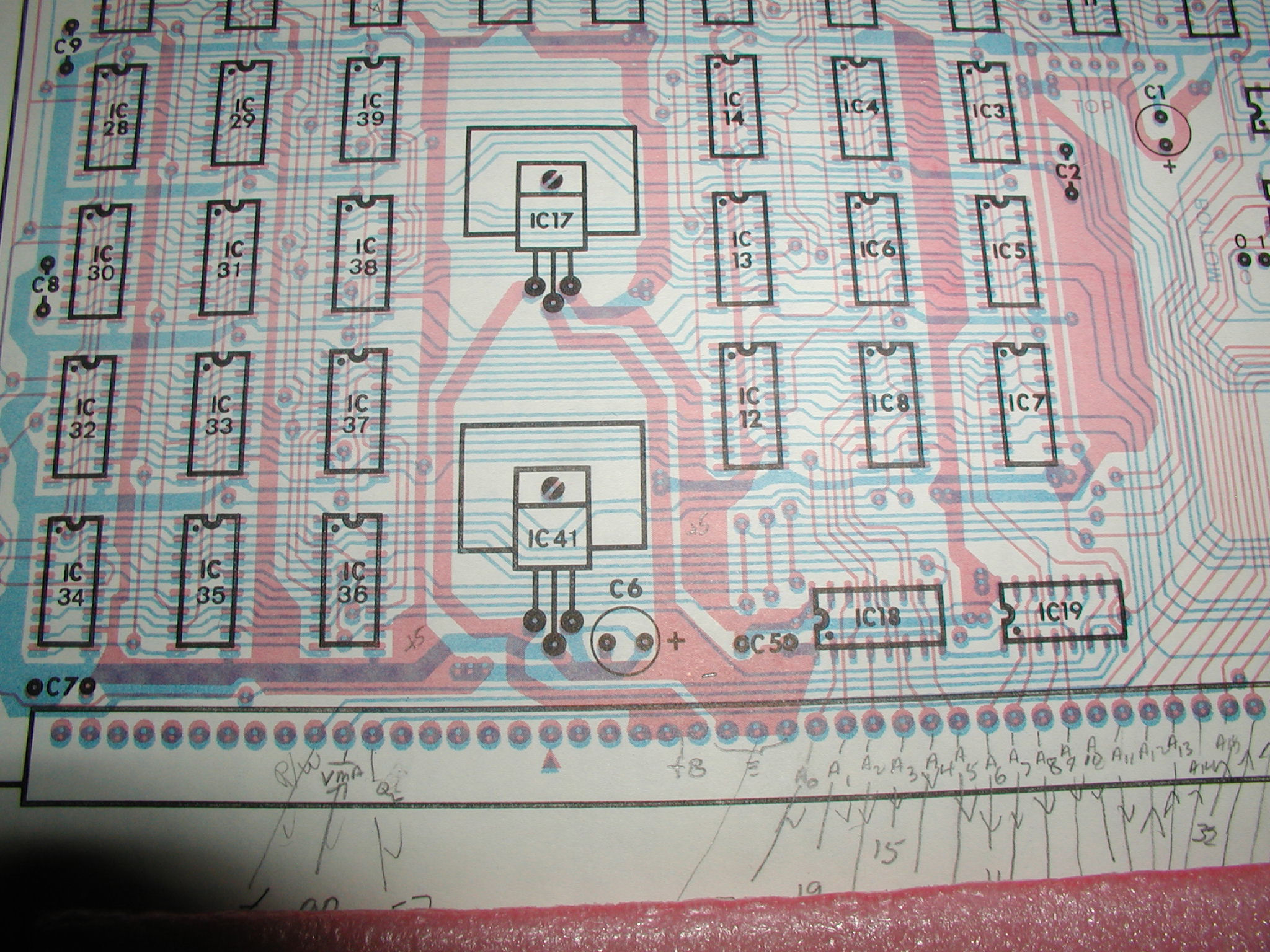
Adding 8K RAM to an Altair 680b using SWTPC MP-M 4K RAM cards wired together to a 680 expansion card? Do do this one needs to make a number of changes but it should be do-able..
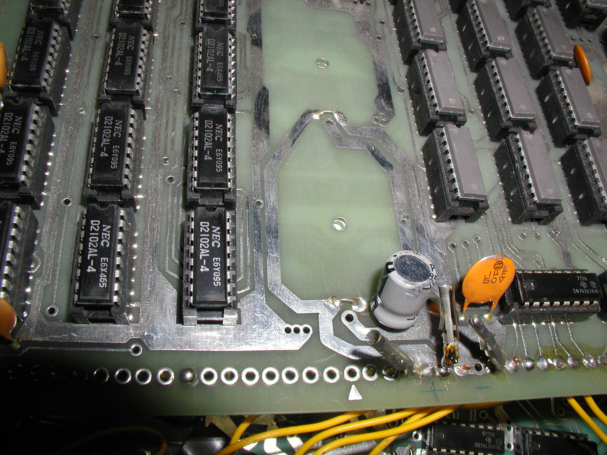
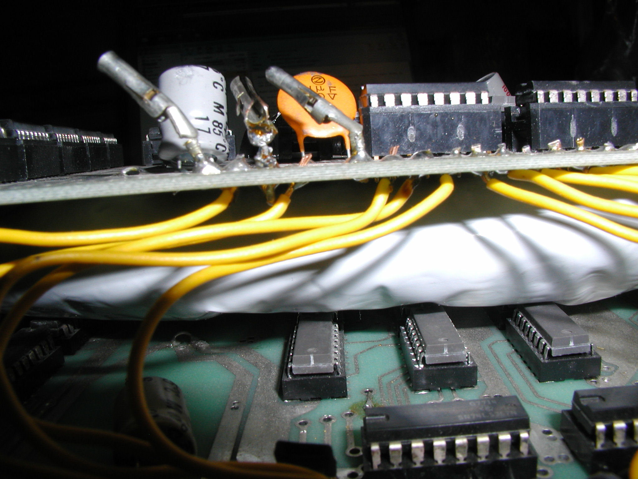
The regulators on both cards in IC 41 (for upper 2K) and IC 17 were removed, and ground was patched to preserve the circuit in place of the regulators. Before I apply power I have to confirm that I should be applying 5V and not 8V, because there are no regulators. Take a look at the bottom of this picture: http://vintagecomputer.n...P-M_layout-scematic.jpg Notice how the original owner has +8 marked next to the ground. That's fine, it matches the schematic, but without the regulators in IC 17 and IC 41, I am not sure if you'd still put 8V to the power connectors, or 5V, which is supposed to be the output of the regulators. With that in mind two questions arise: 1) Do I apply +8V (or +5V?). WHy were the regulators removed? 2) Do I connect power to both the left *and* middle connectors, assuming the right connector is to ground: http://vintagecomputer.n..._regulators-removed.jpg http://vintagecomputer.n...M_7-8V-connectors-2.jpg Answer: 5V, yes connect to the two left connectors. You'd only apply 8V if there was a regulator in place to convert to regulated 5V. If I applied 8V, there'd be nothing to keep the TTL from frying. Pictures of 2 SWTPC MP-M 4K RAM cards hacked for use in a 680 Reply |
|
|
Comparing Altair 680 motherboards |
by Bill Degnan - 06/20/2009 23:58 |
|
First of all the power requirement the SWTPc MP-M boards is 3amps 5V. So far I was not able to find an adequate power supply. I am going to try to find a better solution for RAM.
Strangeness comparing Altair 680 motherboards. Worked with Herb Johnson on this project, he provided detailed analysis vs. my shot gun repair approach. The ePROMS on the Altair 680 with the flat paddles and 1-6 motherboard - not working. DC voltage problem. Should have +5 on pins 15, 12, 13, 23 of each 1702 PROM. Also should have -9 to pins 16 and 24. Took a look at the transistor near Q1 and zener diode to see if it's correctly helping set voltage .. I need to replace transistor Q1's associated SZ 10.9V Zener Diode and the nearby voltage regulator. Tried a 5.1 Zener from Radio Shack, a little low to power the PROMS. This motherboard is a 1-6 (not a 1-6x like my other Altair 680). Side note - Wonder why my other, working Altair 680 with the 1-6X motherboard has a 7805 regulator in Q1, and not a TIP30 pass transistor to regulate the -9 voltage for ROMS. Reply |
|
 680B Negative 9 Volts supply
 |
by William Dromgoole - 06/21/2009 13:26 |
|
I don't have a 680B but I do have the schematics and pc-board layouts for it.
The -9 volt supply is derived from the minus 16 volts that feeds pin 72 of the mainboard. It seems that you could easily remove the TIP-30 at Q1 and replace the transistor with a -9 volt regulator like the 7909 being careful to Lift pin 1 and jumper it to ground and connect Pin 2 to the to the old collector location of Q1 and pin 3 to the old Q1 emitter location. The ground connection could also be made by removing R14 and replacing D4 with a jumper and connecting pin 1 of the IC to the old base connection of Q1. I don't see how a 7805 could be used for a negative voltage. Edit................ "TIP30 regulator A7541 "The emitter of Q1 (TIP30) should supply -9VDC." The actual is approx. -18VDC" This suggests that Q1 is shorted from collector to emitter.The bias for this transistor is supplied by R14 and D4 so its possible that it is not shorted but just biased to full conduction. ">there is a resistor orange/orange/maroon/gold that does not match the other system's. I need to get a chart of the color bar codes." This is probably R14 which should be 330 ohms which is orange/orange/Brown the fourth band is tolerance. Gold is 5% Silver is 1% "33uF50v's next to each other are returning nothing voltage wise where the same caps on the other system report +9 and +7 volts (I can't quite ID them, but they're different)" The schematic shows only three 35ufd caps in the power supply. C-1 is the -9 volt filter which should read -18 given the Q1 problem. C-2 stabilizes the output of D-4 and should read -10 volts. And C-3 is the +5 volt filter at the output of the 7805 regulator VR-1 and should read 5 volts. On my drawing C-1 and C-2 are next to each other so I would expect -9volts and +5 volts rather than +9 and +7 as reported on the working system. billdrom Reply |
|
|
FUA7805 in Q1 on 680 mother bd |
by Bill Degnan - 06/21/2009 17:37 |
|
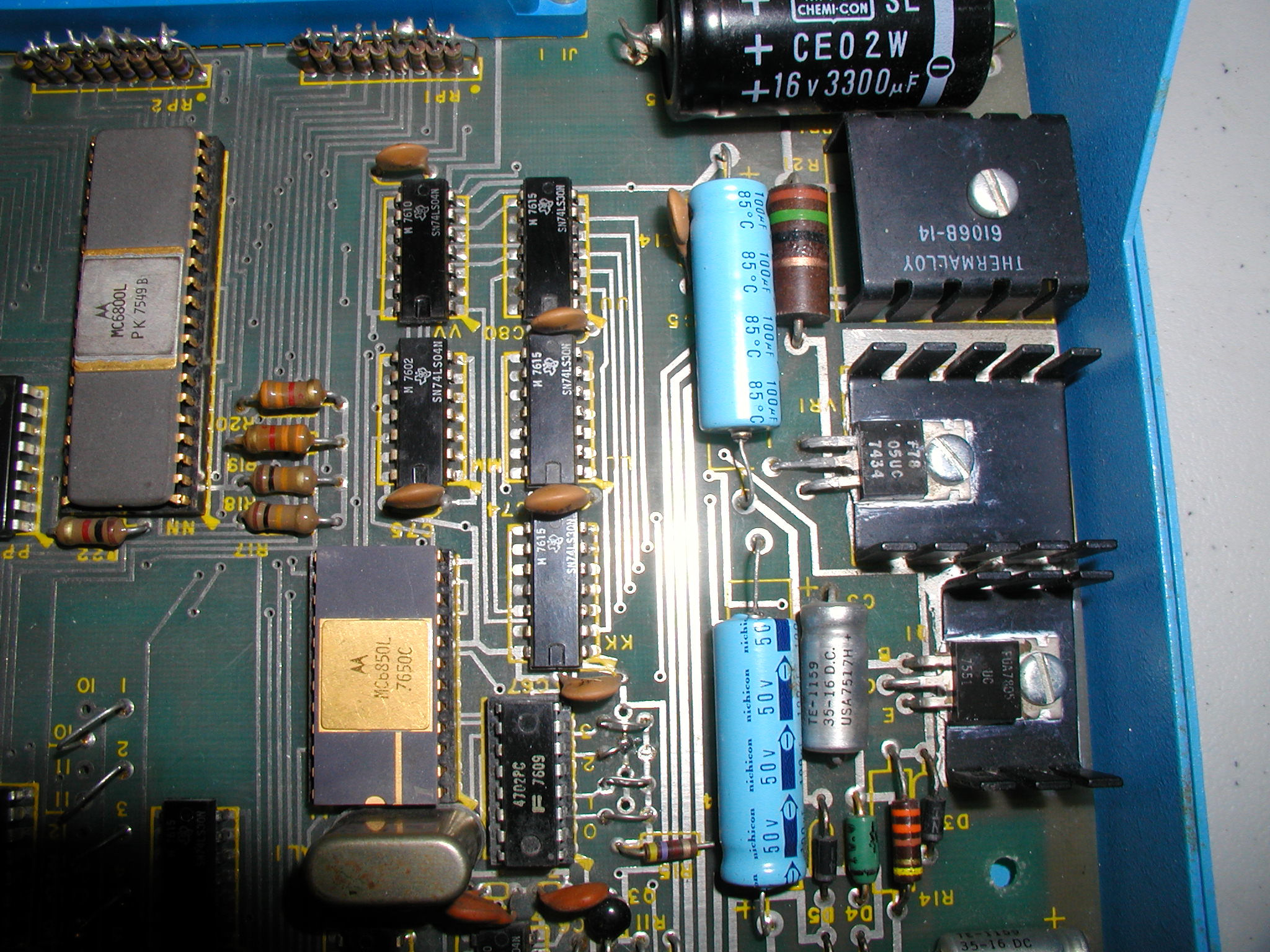
Take a look at this photo:
Motherboard closeup left side The FUA7805 reads -6.3 right/in, -15.9 center, -8.4 center. Herb Johnson was not sure why, it but it works. I have 1702 PROMs in all 4 slots on the motherboard, and they work great. I plan to ask around. Reply |
|
|
FUA7805 in Q1 on 680 mother bd |
by William Dromgoole - 06/21/2009 18:55 |
|
On a 7805 pin 1 is input,pin 2 is Gnd and pin 3 is the output.
What it looks like is happening is pin 2 is connected to -15.9 volts. Pin 1 is - 6.3 volts so input is 9.6 volts positive with respect to pin 2 and the output is 5 volts positive with respect to pin 2 or -10.9 volts.Circuit loading could drag that down(or up) to -8.4 volts. Thats my theory anyway. billdrom Reply |
|
Resources:

Popular Topics and FAQs
Past Issues:
misosys catalog
This image was selected at random from the archive. Click image for more photos and files from this set.